
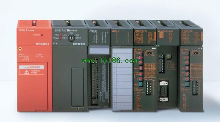
A1SD32ID1 Reader module The time constant of the output circuit, the arrangement of the user statement and the use of the instruction, MITSUBISHI A1SD32ID1
Cable length: 5 meters.
Long distance CPU extension cable.
For QnA/ACPU/ motion control and GOT connection.
AnS, QnAS bus connection, the reader to write program 1 channel connection.
Input status and input information input from the input interface,
CPU will be stored in the working data memory or in the input image register A1SD32ID1.
And then combine the data and the program with CPU.
The result is stored in the output image register or the working data memory,
And then output to the output interface, control the external drive A1SD32ID1.
The response time of PLC is the interval between the time of the change of the external output signal of the PLC and the time of the change of the external output signal which is controlled by it,
Lag time, this is the time constant of the input circuit,
The time constant of the output circuit, the arrangement of the user statement and the use of the instruction,
The cycle scan mode of PLC and the way of PLC to refresh the I/O and so on A1SD32ID1.
This phenomenon is called the I/O delay time effect. Liquid crystal display: 16 characters x 2 lines,
For data access (the state of operation of the central processor, device monitor / change) MITSUBISHI A1SD32ID1. Input type: DC input, positive public end / negative public end.
Input points: 32 points.
Enter the response time: 0.2ms below, below 1.5ms, 5ms below, 10ms the following.
Rated input voltage / current: DC24V/7mA MITSUBISHI A1SD32ID1.
External connection: 1 wire.
According to the external connection mode and the external equipment input and output specifications,
Choose from a rich product lineup.
Finger protection through the upper part of the terminal,
The human body will not be exposed to live parts,
Therefore, the terminal station type remote I/O module can be directly mounted to the machine tool MITSUBISHI A1SD32ID1. Input points: 16 points.
Input voltage and current: 3/7mA DC12/24V.
Input response time: 10ms.
16 point /1 a public side.
Positive and negative sharing.
Output points: 16 points.
Output voltage: DC24V/AC240V, 2A/1 point, 4A/ common end.
Output response time: 12ms.
Output type: relay output.
8 point /1 a public end, 4 points / a public end.
50 point terminal station.
Control solenoid valve required I/O points by the action principle of the solenoid valve can be known,
A single coil solenoid valve with PLC control to 2 input and 1 output,
A double coil solenoid valve requires 3 inputs and 2 outputs,
A button needs an input; a light sensitive switch needs 4 or 2 inputs,
A signal lamp needs 1 output, band switch,
Several bands are required for several inputs,
In general, a variety of position switches are required to take up 2 input points.
MITSUBISHI PLC is the main product in the production of MITSUBISHI motor in Dalian.
It uses a kind of programmable memory for its internal storage procedures,
Execute logic operation, sequence control, timing, counting and arithmetic operations, user oriented instruction,
And through digital or analog input / output control of various types of machinery or production process.
The number of I/O thyristor DC motor control required tube DC motor speed control system is the main form of DC speed regulation,
The thyristor rectifier unit is used to supply power to the DC motor.
PLC control of the DC drive system, the input of the PLC in addition to the main signal outside the signal,
We need to consider the switching signal, the fault signal transmission device, brake signal and fan fault signal.
The output of the PLC mainly consider the speed command signal positive 1~3 level, 1~3 level, allowwing reverse switching signal and brake open signal etc A1SD32ID1..
In general, a reversible DC drive system controlled by PLC is approximately 12 input points and 8 output points,
An irreversible DC drive system requires 9 inputs and 6 output points.
