
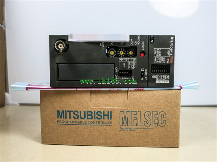
A1SJ72QBR15 MITSUBISHI Network module MITSUBISHI A1SJ72QBR15
A pack of 10.
Applicable models:
AJ65VBTS - - - type.
AJ65VBTCE - - - type.
AJ65VBTCU - - - type.
AJ65ABTP - - - type.
AJ65VBCU- - type. DC input points: 16 points.
Input voltage and current: 7mA, DC24V.
Response time: 10ms.
16 point /1 a public side.
Positive / negative sharing A1SJ72QBR15.
40 point terminal staation.
MITSUBISHI PLC protection and chain procedures.
Protection and chain is an indispensable part of the program, must be carefully considered.
It can avoid the control logic confusion caused by illegal operations A1SJ72QBR15.
MITSUBISHI PLC initialization procedure. After MITSUBISHI PLC on power, the general need to do some of the initial operation,
In order to start making necessary preparations, to avoid the wrong operation of the system A1SJ72QBR15.
The main contents of the initialization program are: to some data area, counter and so on,
Data needed to restore some of the data area,
Set or reset some relays,
For some initial state display, etc..
MITSUBISHI PLC program simulation debugging
The basic idea of program simulation debugging is,
In order to facilitate the form of simulation to generate the actual state of the scene,
Create the necessary environmental conditions for the operation of the program MITSUBISHI A1SJ72QBR15.
Depending on the way the field signals are generated,
The simulation debugging has two forms of hardware simulation and software simulation MITSUBISHI A1SJ72QBR15.
3C-2V/5C-2V coaxial cable single bus remote I/O network (remote I/O station).
Q mode.
When the programmer input programinto the user program memory,
Then CPU according to the function of the system (the system program memory to explain the compiler),
Translate the user program into PLC internally recognized by the user to compile the program MITSUBISHI A1SJ72QBR15.
Input status and input information input from the input interface,
CPU will be stored in the working data memory or in the input image register.
And then combine the data and the program with CPU.
The result is stored in the output image register or the working data memory,
And then output to the output interface, control the external drive.
Semiconductor circuit with memory function.
System program memory and user memory.
System program memory for storing system program,
Including management procedures, monitoring procedures, as well as the user program to do the compiler to compile the process of interpretation.
Read only memory. Manufacturers use, content can not be changed, power does not diisappear A1SJ72QBR15.
User memory: user program storage area and work data storage area.
Composed of random access memory (RAM). User use.
Power cut off. Commonly used efficient lithium battery as a backup power supply, life is generally 3~5 years.