Brand sort
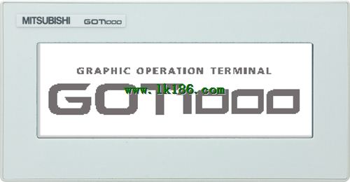
Sale GT1030-LWDW2 MITSUBISHI GT1030-LWDW2
Brand:
MITSUBISHI(Mitsubishi)
Country: JAPAN
Name: 4.5 Inch Touch Screen
Model: GT1030-LWDW2
Market price: U.S.$ 0
(The following are the market open price not sales price!)
(The following are the market open price not sales price!)
MITSUBISHI GT1030-LWDW2
For QCPU (Q) / transport controller CPU (Q Series) the bus (2 channel) thin type unit.
Applicable models: GT15, GT16, GT27, GT25. Analog channel: 8 channels.
Input / output (resolution): 0 ~ 4000.
Conversion speed: 100ms/8 channel.
Analog module installation.
Power supply: AC170V ~ 264V.
According to the control requirements of the system, using the appropriate design method to design MITSUBISHI PLC program GT1030-LWDW2
Procedures to meet the requirements of system control as the main line,
Write one by one to achieve the control function or the sub task of the program,
Gradually improve the functions specified by the system.
MITSUBISHI PLC detection, fault diagnosis and display and other procedures GT1030-LWDW2.
These procedures are relatively independent, generally in the basic completion of the program design and then add .
Hardware simulation method is to use a number of hardware equipment to simulate the generation of the signal,
The signals are connected to the input end of the PLC system in a hard wired way, and the timeliness is strong GT1030-LWDW2.
Software simulation method is in the MITSUBISHI PLC in the preparation of a set of simulation program,
The simulation provides the field signal, which is simple and easy to operate, but it is not easy to guarantee the timeliness .
Simulation of the process of debugging, debugging method can be used to segment, and the monitoring function of programmer. Input voltage range: DC110/125V.
Output voltage: DC5V.
Output current: 8A.
For Q4ARCPU.
The control module monitors the power supply, the error
CPU state,
And its own error state.
It sends out
Error signal a6raf and open the corresponding
Relay output.
I/O points is an important indicator of PLC.
Reasonable selection of I/O points can not only satisfy the control requirements of the system,
And the total investment of the system is the lowest.
The input and output points and types of PLC should bee determined according to thhe analog quantity and switch quantity of the controlled object,
Generally an input / output element to take up an input / output point MITSUBISHI GT1030-LWDW2.
Taking into account the future adjustment and expansion,
In general should be estimaateed on the total number of points plus the amount of spare 20%~30% MITSUBISHI GT1030-LWDW2.
The following describes the centralized control system I/O points of the estimate.
GT1030-LWDW2 Operation manual/Instructions/Model selection sample download link: /searchDownload.html?Search=GT1030-LWDW2&select=5
...more relevant model market price >>>>
Related products
MITSUBISHI
4.5 Inch Touch Screen
GT1030-LBDW
Series introduction: set a numer of as
MITSUBISHI
4.5 Inch Touch Screen
GT1030-LWLW
Series introduction: set a numer of as
MITSUBISHI
4.5 Inch Touch Screen
GT1030-LBLW
Series introduction: set a numer of as
MITSUBISHI
4.5 Inch Touch Screen
GT1030-LWD
Series introduction: set a numer of as
Related download


 next one:
  Last one: